
How to: Know for Certain Your Medical Circuits are Safe
More than almost any other type of circuit, it’s critical to ensure that it is designed and developed specifically for the medical industry. Here are some essential things to consider to make certain your printed circuit boards (PCBs) are completely safe and effective.
Signal Integrity
Signal integrity is critical for medical circuits. That’s because electrical signals must stay clear of interference and noise while moving along the traces. The layout and routing selection must follow best practices to minimize even the slightest bit of noise on traces. A knowledgable provider like Tramonto Circuits will ensure this is the case.
EMI/EMC Compliance
EMI/EMC compliance is vital for circuits used in medical devices. Electrical interference can impact how the device operates along with other nearby equipment and systems.
Power Consumption
Power consumption is a crucial consideration when designing medical circuits. Specific devices require low power levels for portability or to extend battery life. It’s critical that the board layout not limit power efficiency gains. Plus, all materials used must minimize energy needs without negatively impacting performance. An experienced medical PCB designer and manufacturing company like Tramonto Circuits can address these factors.
DfM Design
Medical circuit boards must meet tight standards for precision and quality as part of an IPC 6012 Class 3 build. DfM ensures the most stringent aspects of the design are met in the manufacturing process.
Dependability
Of course, high reliability is critical for medical circuit boards. The failure of a medical device could put someone’s life at risk. Designers and manufacturers must select parts and materials that can withstand the operating environment. Temperature fluctuations and humidity levels must be considered to minimize premature degradation or failure.
Quality Control
Medical device manufacturers must consistently employ the highest level of quality control to ensure they meet the required standards and specifications. The manufacturing process must be carefully monitored and controlled to ensure the PCBs meet specified tolerances, dimensions, and electrical requirements.
Traceability
Medical device makers must be able to track every device component from the original design to the finished product. This requires strictly following traceability protocols, including:
- Component tracking
- Lot tracking
- Serial number assignment
- And more.
Medical device makers must maintain complete documentation of the development and manufacturing process, including material traceability, testing results, and validation reports. Tramonto Circuits has extensive experience with all forms of documentation.
Material Selection
The materials used in medical PCBs must be carefully chosen to ensure they align with the device’s intended use, sterilization method, and regulatory requirements. They must be free of contaminants and impurities. The materials used in a medical PCB must also be safe and reliable. They should be durable and flame-retardant. All must be UL-approved, as well.
Environmental Controls
The manufacturing location must be carefully controlled to ensure that the circuits are made in a clean environment with no contaminants or particles that could negatively affect performance or safety.
Testing and Validation
Medical circuits must be tested and validated to ensure they comply with standards and meet specifications. This includes testing for electrical and environmental performance, along with compatibility with the other components of the device.
Medical devices are life and death. You can’t take chances with a designer or manufacturer that doesn’t have extensive industry knowledge. Tramonto Circuits has decades of experience designing and developing custom circuits for a wide range of medical device manufacturers. Contact one of our helpful and knowledgeable representatives to learn how we could support your organization.

Medical Device Regulations for PCBs: What You Must Know
Adhering to industry-specific rules and regulations is essential for most products. It’s even more critical for manufacturers creating printed circuit boards (PCBs) for medical devices and device makers to follow them to the letter to ensure the equipment performs as intended. It’s a matter of life and death.
This guide explains what medical device manufacturers and the circuit producers that support them must know about regulations related to developing safe and effective PCBs and medical equipment.
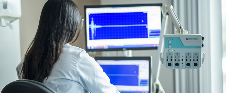
Medical Devices Dependent on Circuit Boards
Devices that are heavily reliant on circuits include:
- Blood pressure monitors
- Heart monitors
- Pacemakers
- Thermometers
- Cochlear implants
- Imaging and diagnostic instruments
- EMG (electromyography) activity systems
- Neurostimulators
- Handheld monitors.
These devices must function precisely all the time to help diagnose and treat patients. They require many inspections during the manufacturing process and once the machines are in use. Several bodies across the globe have issued guidelines for these instruments.
What are the Medical Device Regulations for PCBs?
Authorities like the Institute for Printed Circuits (IPC), the International Organization for Standardization (ISO), and the U.S. Food and Drug Administration (FDA) have all released standards related to circuit boards used in medical equipment. The guidelines include all aspects of the development and manufacturing process all the way to final approval. It’s mandatory to follow all these regulations during medical PCB assembly to ensure they are reliable and don’t cause harm to patients.
Let’s go deeper into each of these organizations and their regulations.
IPC
The Institute for Printed Circuits is an organization that regulates the assembly and production of electronic components and assemblies. The group has developed and released several critical standards:
- IPC-A-600: Establishes the minimum acceptability requirements for printed boards.
- IPC-A-6012: Describes the qualification and performance requirements for PCBs.
- IPC-A-610: Explains the requirements for acceptable electronic assemblies.
The IPC also has standards for:
- Wire harnesses
- Soldering
- Enclosures
- Cables.
Visit the IPC website to learn more about applicable standards.
ISO
ISO is the acronym for the International Organization for Standardization. The group develops and publishes a range of standards related to the design, manufacture, and testing of circuit boards.
The ISO 9000 standard is mandatory for original equipment manufacturers (OEMs) to certify the safety of medical equipment and its proper function. ISO 13485:2016 is an updated quality management system for MedTech devices centered on current industry practices. It places a strong focus on risk management along with risk-based decision-making. It also provides information related to industry regulatory concerns.
FDA
The United States Food and Drug Administration’s (FDA) Center for Devices and Radiological Health (CDRH) imposes laws on companies that manufacture, re-label, re-package, and import medical devices in and into the U.S. In addition, CDRH monitors electronic products that emit radiation, including X-ray equipment, lasers, ultrasound devices, and others.
FDA categorizes medical devices into three classes:
- Class 1 devices include adhesive bandages, sunglasses, IV (intravenous therapy) stands, and other things considered relatively low risk.
- Class 2 devices include intermediate-risk instruments like powered wheelchairs, syringes, surgical masks, and other similar items.
- Class 3 devices include many high-risk items that use PCBs such as heart valves and implantable neuromuscular stimulators. This category is the most stringent and closely monitored by the agency.
The many facets of FDA compliance are organized into the following categories:
Establishment registration
Domestic and foreign manufacturers must register with the Food and Drug Administration. This takes place electronically unless the organization issues a waiver. Manufacturers must complete an annual verification of their registration information between October 1 and December 31 of each year. Overseas manufacturers must also appoint a U.S. representative.
Medical device listing
Manufacturers must comply with medical device listing requirements, including the following types of businesses:
- Contract manufacturers (CM)
- Contract sterilizers
- Manufacturers
- Manufacturers of components and accessories sold directly to end-users
- Relabelers and repackagers
- Remanufacturers
- Reprocessors of single-use devices
- Specification developers
· United States manufacturers of devices for export only.
Quality system regulation
Quality system regulation involves defining and meeting requirements related to various aspects of medical devices, including:
- Designing
- Fitting
- Labeling
- Maintaining
- Packaging
- Procurement
- Production
- Storing.
Manufacturing facilities are subject to FDA inspections to ensure compliance with their standards.
Labeling requirements
According to the FDA, labeling includes the physical device label, its description, and any additional informational text that is included with the device.
Medical device reporting (MDR)
The fundamental rationale behind the Food and Drug Administration’s MDR regulation is to identify significant adverse issues related to medical devices and to monitor them on an ongoing basis. It’s a requirement to notify the organization about anything that may have caused severe problems, injuries, or death. All device malfunctions must also be reported. The goal is to uncover and fix issues as soon as possible.
Premarket notification 510 (k)
This law, the Medical Device User Fee and Modernization Act, allows the FDA to conduct medical device premarket notification 510 (k) reviews and charge fees for it. (Certain businesses could be eligible for reduced costs.)
Under this law, a business cannot distribute a device requiring 510(k) submission until the FDA demonstrates valid equivalence.
Premarket approval (PMA)
Class III products require premarket approvals because they present a significant risk of illness and injury and cannot be compared directly to less-risky class I and II products. Premarket approval is a highly complicated process that includes submitting clinical data to support any claims about the device.
Medical Device Regulations: The Final Word
Complying with the vast array of PCB-related regulations is complicated. That’s why you shouldn’t go it alone or work with an inexperienced circuit designer or manufacturer. Turn to the experts at Tramonto Circuits to get the support you deserve. Contact a friendly and knowledgeable representative to learn how we can support you.
10 + 1 Circuit Design and Manufacturing Issues and How to Prevent Them
Printed circuit boards (PCBs) are key parts of many electrical devices, connecting critical components. Global demand for circuits has risen exponentially in recent years, and many less-than-reputable actors have entered the industry.
This guide explains common PCB issues (often found in circuits produced by less-experienced providers) and how to avoid them so the devices you use them in perform as intended, providing a high level of dependable service for years to come.
What Is PCB Failure?
PCB failure occurs for many reasons. The end result is that the PCB no longer functions as intended, which can lead to device breakdowns or complete failure. Because PCBs are used in many electronic devices that could malfunction in perilous situations, such as medical wearables, airplane, automobile, and hospital equipment, any possible issues must be identified and prevented — and when they happen, quickly fixed.
Any company looking to keep their electronics running smoothly can prevent PCB failure — and recover from it when it occurs — by understanding why it happens.
The complexity of the PCB design and manufacturing processes introduces many opportunities for issues to arise. Some failures result from design mistakes, such as inadequate clearances or incorrect measurements. Design errors can negatively affect the functioning of the products they’re used in. Others may be the result of issues in manufacturing, such as drilling errors or over-etching. Manufacturing mistakes often result in catastrophic consequences.
The good news is that most of these problems can be avoided by working with professionals who have a deep knowledge of the PCB design and development process and know about common PCB manufacturing problems and how to avoid them.
Following strict design and manufacturing rules and considerations can prevent component failure, connection issues, and other circuit board-related problems.
Here are some common things you may encounter if you work with less-than-reputable circuit manufacturers or those not experienced in your industry.
1. Plating Voids
Plated through-holes are copper-coated holes in a PCB. They allow electricity to move across the circuit. A PCB board fabricator drills holes through the circuit board to create them. Then, through an electroplating process, a layer of copper foil or a copper coating is added to the surface of the material and along the walls of the holes. This disposition process places a thin layer of electroless copper onto the circuit. Finally, additional layers of copper are added and etched to create the circuit image.
The deposition process is not a perfect one. Sometimes, it results in voids in the plating, which are gaps or holes. The plating voids are problematic because they prevent the electrical current from passing through the hole, making it ineffective.
The plating voids happen because of the following:
· Contamination
· Air bubbles in the material
· Inadequate cleaning of the holes
· Insufficient catalyzation of the copper in the deposition process
· Rough hole drilling.
Defects can be avoided by cleaning the material properly after drilling and closely following the manufacturer’s drill directions during use. You can avoid these issues by working with a well-qualified and experienced PCB manufacturing company.
2. Inadequate Copper-to-Edge Clearance
Copper is an incredibly conductive metal. It’s also relatively soft and vulnerable to corrosion. To prevent corrosion, the copper is covered with other materials.
The issue: when a PCB is trimmed, part of the coating can also be cut, exposing the copper below. This negatively impacts the board’s functionality, resulting in shorts and shocks.
This issue can be prevented by ensuring the space between the edge of the copper and the edge of the board (often referred to as the copper-to-edge or plate-to-edge clearance) meets the standards for the type of board being manufactured. A complete design for manufacturability (DFM) check by an experienced manufacturer like Tramonto Circuits typically identifies possible problems.
3. Poor Quality Soldering
Improper soldering during the PCB assembly process can result in significant consequences. One example of this can happen when a technician doesn’t heat the solder enough, referred to as cold soldering, which can result in circuit failure. In addition, when moisture enters the soldering process, it can contaminate the PCB pad and other components.
This contamination can cause PCB components to experience connection problems and possibly burn up. The best PCB manufacturers use visual or enhanced X-ray inspections to find bad soldering.
4. Slivers
Slivers are narrow wedges of copper or solder masks produced during printed circuit board manufacturing. These slivers are often created during the etching process.
The slivers can connect to other pieces of copper or expose copper plating that the solder mask should protect. The first issue can result in a short. The second can cause the copper to corrode over time. Both of these things can reduce the life of the circuit board.
Slivers can be prevented by designing boards with sections of minimum widths. A manufacturer can identify slivers with a DFM check.
5. Missing Solder Mask Between Pads
The solder mask is on top of the circuit board’s copper layer. It prevents the copper traces from accidental contact with other metal, solder, or conductive bits. It also acts as a barrier between the copper and the environment, which prevents corrosion and protects the circuit board’s handlers from electrocution.
In some circuit boards, the solder mask may be partially or entirely missing. This exposes the copper and can result in solder bridges forming between pins. When this happens, it can result in a short circuit and reduced corrosion protection, which can negatively impact the functionality and longevity of the PCB.
This defect is typically the result of a design oversight. The solder mask is undefined, or the settings for a larger board are carried over to a smaller one. This results in pad holes that are too large for the smaller printed circuit board.
All this can be prevented by checking the design before manufacturing, something a reputable manufacturer like Tramonto Circuits will do.
6. Acute Angles in Circuits
Acid Trap is the common term for acute angles in a circuit. The acute angles trap acid during the circuit board etching process. This allows the acid to build up in the corner of the angle, which keeps it there for longer than necessary. In this situation, the acid eats away more than intended, which can compromise a connection. This results in a defective circuit, which can cause severe problems in the future.
Experienced designers are aware of the issues related to acute angles and circuit boards. They are knowledgeable enough to avoid them.
7. Badly Manufactured Components
Another cause of printed circuit board failure happens when the engineering team uses poorly manufactured components. During the PCB production process, any physical damage because of the wrong components can harm the PCB, leading to power failure. Common circuit assembly defects and faults from poorly manufactured components include connection issues and loose parts. Also, residual flux (a substance used during soldering) left on a circuit panel can cause significant damage, making it necessary to repair the circuit board. Experienced manufacturers always use the right high-quality components in their PCBs.
8. Starved Thermals
Thermals are small traces surrounding pads. They’re used to connect pads to the plane. They allow the pads to disperse heat effectively and are critical for the soldering process.
Voids between the thermal and the rest of the plane — or the thermal and the pad — can lead to an incomplete connection. When this happens, it reduces the effectiveness of the heat transfer system the thermals create.
Starved thermals take much longer to transfer heat from pads to the rest of the plane, which can be problematic during soldering or if the circuit is under heat stress. A thermal pad with improper heat transfer may solder in an unusual way. It will also take unusually long to reflow, extending the assembly time. After manufacturing, circuit boards with starved thermals may deliver insufficient heat transfer and are often prone to overheating and heat damage.
The source of these issues can most often be traced back to the manufacturing process. These thermal connections are usually designed correctly in a computer-aided design (CAD) system but are somehow manufactured with a reduced connection to the plane. Manufacturing problems during thermal molding or machining, including over-machining or improper molding, can all lead to this issue. When it happens, it’s usually best to replace the thermal.
An experienced circuit manufacturing company like Tramonto Circuits can prevent faulty thermals, identify them when they happen, and replace them before any harm can occur.
9. Electromagnetic Issues
Electromagnetic compatibility and electromagnetic interference are two problem areas when it comes to circuit board design. Electromagnetic compatibility (EMC) is the generation, propagation, and reception of electromagnetic energy. Electromagnetic interference (EMI) is an unwanted effect of EMC that can cause damage. Too much EMI can cause products to react intermittently and not work as intended. It is typically the result of a design flaw.
EMI can be lowered by expanding the circuit board’s ground area and compartmentalizing the board and signals specifically for EMI. In addition, 90-degree angles must be avoided for most components because they can increase EMI interference. Also, use shielded cables during cable assembly and metallic packaging to absorb EMC and reduce EMI.
10. Environmental Contamination
Environmental factors can negatively impact PCB quality. PCBs exposed to dust, moisture, heat, and cold are likelier to fail. For instance, changes in temperature can make elements on the circuit contract or expand, which could damage or warp the soldering joints and boards themselves. Consulting with an experienced manufacturer like Tramonto Circuits can help mitigate these concerns before boards are fabricated.
Dust around a circuit board can build up over time, clogging the board, which can cause it to overheat. Also, moisture can result in corrosion, rust, and oxidation, damaging the PCB.
Plus 1: No or Inadequate DFM Check or Poor Communication
This guide reveals many things that can go wrong when designing and manufacturing PCBs. The good news is that all of them are preventable. That is why it’s so critical to partner with an experienced PCB manufacturer that runs DFM checks on the designs before they begin building them.
DFM is short for Design for Manufacturability.
DFM checking is the process of reviewing a circuit board layout to identify and minimize any issues that could occur during the fabrication and assembly process. DFM ensures that the design will result in a consistent product that performs as expected dependably. Unlike other standards that only consider how the PCB will potentially work, DFM looks at how the circuit board could break down.
Minimizing these issues requires a specific kind of expertise. Only a few of the design flaws covered in this piece are flagged by CAD software. That’s because it’s not designed to look for these possible issues. A sound DFM check, however, is focused on identifying these potential problems, drawing from an extensive and specialized database of design checks. All these checks may not apply to your specific circuit board, especially if it’s experimental. However, they’re critical to consider before manufacturing begins.
While DFM checks are a relatively common practice for most designers and manufacturers, many don’t understand or communicate design gaps properly. This can result in severe problems down the road.
That’s why you must partner with a custom PCB company like Tramonto Circuits that provides a thorough DFM check backed by a knowledgeable, communicative, and professional staff that will walk you through any issues that may arise with a circuit design or during the manufacturing process. Contact the experts at Tramonto today to find out how we can support you in developing circuits you — and your end users — can depend on.
Challenges of Flexible Circuit Assemblies
Are you finding it challenging to procure suitable flexible circuits? It’s a fast-changing industry, and it can be difficult to stay up-to-date on the latest trends. This guide explains everything you need to know to have a complete understanding of the challenges associated with manufacturing flexible circuits. It will provide you with the information you need to find the right supplier for you.
What are Flexible Circuits?
Flexible circuits, also known as flex circuits, are electronic circuits made of flexible materials such as plastic and polyimide. They are widely used in various industries, including aerospace, medical, and automotive, because of their ability to bend and conform to different shapes and sizes.
What is the Demand for Flexible Circuits?
According to a recent report by Maximize Market Research, the global market for flexible circuits was $32.65 billion in 2022. That’s expected to grow by 8.23 percent annually to $56.81 billion in 2029. Companies that use flexible circuits could find it challenging to procure the components they need as demand increases.
What are the Challenges Associated with Manufacturing Flexible Circuit Boards?
The assembly of flexible circuits presents several challenges that manufacturers must overcome to ensure reliability and functionality.
Equipment Challenges for Manufacturing Flexible Circuits
One of the biggest challenges of flexible circuit assembly is how complex the process is. Unlike rigid circuit boards, which are typically built using automated machines, flexible circuits require additional tools to utilize the automated equipment because of their flexibility. These added tools and processes reduce the risk of errors and defects, which could lead to costly rework or even product failure.
Flexible Circuits: Design Challenges
The design of flexible circuits can also pose challenges during assembly. Flex circuits often have complex and intricate designs that require precise assembly techniques to ensure their functionality. The design must also take into account the flexibility of the circuit board, which can affect the placement of components and the routing of traces. This requires careful planning and coordination between the design and assembly teams, which requires highly skilled designers and operators.
Flexible Circuits: Material Requirements
The materials used in flexible circuit assembly also present challenges. Flexible circuits are often made using thin and delicate materials that require careful handling to avoid damage. In addition, the material must be able to handle the high temperatures needed to solder components on the circuit without any damage to the circuit itself.
In short, you need a manufacturer that understands the complex material requirements of building circuit boards.
Circuit Boards: Dependency on Experienced Talent
The final challenge of flexible circuit assembly is the need for highly trained personnel. It requires designers and operators who understand the process very well and can plan the tools accordingly, as each circuit has its own unique requirements.
Additionally, the manufacturing equipment must be regularly maintained by experts to ensure it remains in good working condition. It may need to be adjusted periodically during the assembly process.
Flexible Circuit Boards: The Bottom Line
In conclusion, the assembly of flexible circuits presents several challenges that manufacturers must overcome to ensure their reliability and functionality. These challenges include the complexity of the process, the need for specialized equipment, the design of the circuit and the materials used, and finding the right people to get the job done. However, with proper planning, training, and equipment, the best manufacturers can successfully assemble flexible circuits that meet the needs of their customers.
Exploring Multi-Layer PCBs: Benefits and Applications
Printed Circuit Boards are the backbone of modern electronic devices, to say the least. Single-layer PCBs are widely used, though as technology evolved, the demand for more complex PCBs increased. Multi-layer PCBs have played an integral role in fulfilling this need for more complex electronic systems and they come with many benefits.
Multi-layer PCBs can have between 3 and 20 layers. The more layers, the more density of components and interconnections is allowed. More layers actually have made it possible for smaller yet more powerful technology to be made, like power planes, ground planes, signal layers, smartphones and tablets, automotive electronics, aerospace systems, and many more technologies. Additionally, they can reduce assembly costs by allowing the integration of other components like microcontrollers, sensors, and memory modules on a single board.
Multi-layer PCBs also reduce electromagnetic interference (EMI) and noise issues. This makes them ideal for complex electronic applications like motherboards and radio frequency boards.
These PCBs also have great signal integrity. Additional layers allow for shorter and more direct signal paths, reducing the possibility of distortion and signal loss. High-speed applications need this type of reliability for better data transfer rates and reduced transmission errors.
Have we convinced you yet that multi-layer PCBs are great? Because there are even more benefits. These PCBs offer improved thermal management, so there is more surface area for heat dissipation which works great for hot components or cooling mechanisms. Efficient thermal transfer prevents overheating and extends the lifespan of the components in tough environments.
Multi-layer PCBs really revolutionized the field of electronics with all these benefits and expanded the use of more compact electronics. This type of PCB will remain at the forefront of developing more sophisticated technologies.
Tramonto Circuits has many years of experience working with multi-layer PCBs and can help you with your manufacturing project. Contact us today for help with your multi-layer PCB design.
The Evolution of Circuit Board Manufacturing Techniques
As the technology in which circuit boards are used has evolved, so have the circuit boards themselves. We won’t age ourselves, but at Tramonto Circuits, we have seen circuit board manufacturing change in many ways since we opened up for business.
Did you know that the earliest circuit boards were made using a technique called point-to-point construction? This involved manually wiring components together on a board. Can you imagine how long that took? Likewise, it posed the risk of human error. Engineers began seeking and testing solutions that would open the doors for mass production.
This led to a production technique called wire wrap. This meant wrapping wires around posts on the circuit board and soldering them in place. This was an improvement, but this process still required too much skill and time.
Enter the 1960’s, the era of printed circuit board (PCB) manufacturing. PCB manufacturing prints a circuit pattern onto a board using a photographic process, then etching away unnecessary remaining copper to leave behind the essential circuits. PCB manufacturing remains the industry standard, but this production method, of course, has also evolved since the 1960’s.
The 1980’s presented surface mount technology, which allowed components to be mounted directly onto the board’s surface, rather than being inserted into holes. This technology played a huge role in making circuits more compact and it brought the process much closer to automation.
Now, PCB manufacturing is hugely automated, but it still involves multiple stages. There is software to create the circuit design, there are special printers to print it on the board, there is a machine that applies a solder paste, and machines that place the components on the board. There are also specialized ovens to melt the solder. Technology has significantly improved the process and quality of circuit boards.
We are currently on the cusp of what could be a new era of PCB manufacturing, and that is the 3D printing era. It is still being heavily tested and explored, but it could revolutionize the process and allow for more complex designs.
When working with a partner to manufacture your circuits, you want a trusted company that knows all the ins and outs of circuit design. Contact Tramonto Circuits for true expert advice every step of the way.

How to Properly Test Functionality of Electronic Circuits
The smallest malfunction in a circuit can have significant consequences, especially when going through the manufacturing process. Testing is a huge part of what we do at Tramonto Circuits because we want our customers to safely avoid setbacks that will delay their product getting to market. Here are some of the best practices we employ when it comes to testing electronic circuits.
Visual inspection
We always first check for any loose connections, damaged or burnt components, or signs of physical damage. All components should be in their correct locations, too, and there should be no short circuits between the tracks.
Power-up
We then connect the circuit to power and switch it on, using a multimeter to measure the voltage to make sure it is operating within the expected range.
Functionality test
We will simulate the circuit’s operating conditions and verify that it performs as it will be intended. We take into account all factors of what this circuit’s purpose will be, including temperature and other environmental factors, timing, sensors, and more.
Long-term reliability
A circuit has to continue to function correctly over an extended period. Therefore, we’ll subject the circuit to continuous operation for several weeks to check for any failures.
Thorough electronic circuit testing can save time, money, and even lives. Work with Tramonto Circuits to make sure your next project is in good hands.

3 Common Sources of Manufacturing Delays
The year is 2023 and all we seem to continue hearing about is one supply chain crisis after another. Tramonto Circuits has been around long enough to see and adapt to other world crises. A global pandemic, of course, is one major source of manufacturing delays. However, there are themes that most frequently can be the source of delays, no matter what is going on at the current point in history. Here are those common sources of manufacturing delays to look out for.
Late Shipments
Limitations in raw materials or components can lead to late shipments and if workers don’t have what they need, they can’t move forward and there will be a slowdown in production. This can also lead to an increase in inventory costs as finished goods cannot be shipped out until the missing items arrive.
RFQ’s
A Request for Quote (RFQ) helps allow a supplier to maximize their sales at an appropriate price point, considering all variables. These RFQ’s can cause manufacturing delays if the process of gathering quotes from suppliers takes too long. Sometimes an RFQ process can result in selecting a supplier who cannot deliver on time, further adding to the delay.
Order Acknowledgements
Order acknowledgments are simply the process of confirming and verifying customer orders. If they’re not completed in a timely manner, that can cause delays on top of confusion about details and the need for clarification. Even worse, inaccurate information on the order acknowledgment can also cause production errors that then lead to rework.
The team at Tramonto Circuits has learned a lot about these common delay triggers and has mastered mitigating these risks as best as we can. We’ve prioritized quick quotes and get 24-hour quotations done 98.9% of the time. Our on-time delivery rate is 98.15% because we know to look out for these risks and do what we can to prevent them. Move your manufacturing project along at the rate you want it to by working with Tramonto Circuits today.

What Data is Required for a PCB Design Quote?
Tramonto Circuits provides 98.9% of its quotes within 24 hours. To put it simply, we’ve nailed down the quote process for PCB design pretty well over the years. Here’s what you should expect to be able to provide in order to get the most accurate quote for your PCB design project.
Schematic
No matter what stage of development your project is at, one bare minimum requirement your PCB provider will need to know so that they can lay out services is a schematic. This can be a simple JPG or a full CAD schematic file. Just make sure your resolution is high enough so that the information is legible.
Bill of Materials (BOM)
BOMs most frequently come in Excel spreadsheets but other files are acceptable. This should list each component that will be used in the assembly. Even better if you can include the manufacturer, part number, and quantities. Missing details may lead us to ask for more specific information because these details will affect the amount of surface area required and layer count.
Placement Drawing
A basic dimensional view that shows the X-Y dimensions of the PCB will help your provider understand how the available PCB surface area will be organized. The more dimensions you can provide, the better, but for the most part, a basic model showing the locations of components will go a long way. These drawings are often called “key placement” documents, too.
Tramonto Circuits has a handy file upload on its quote submission form to allow users to provide this information to help guide us to an accurate quote for you. Submit yours today and get your quote within 24 hours.
3 Tips for Working Through Supply Chain Issues While Manufacturing
Manufacturers of all types have experienced quite their share of supply chain hiccups in recent years. At Tramonto Circuits, we’ve gone through many years of experience working around all kinds of disruptions in the world and managed to maintain top-notch delivery rates and quality for our customers. Here are our suggestions for how you can best navigate through supply chain disruptions during your manufacturing process.
Tip #1: Find a trusted partner with great delivery rates
The times sure have changed and this time in the history of supply chain issues is not the same as others. However, a company with a track record of experience working through shortages is going to be your best bet. When seeking a trusted manufacturing partner, ask what their on-time delivery rate is. Tramonto Circuits has a 98.15% on-time delivery rate, even through the delays of today.
Tip #2: Use predictive analytics where possible
Do you know yet exactly how supply chain levels may affect your project’s timeline? Predictive analytics can give you insights into buyer patterns in relation to all kinds of disruptions so you know how supply levels can affect your retail sales. Tramonto Circuits helps its partners know what they can expect along their manufacturing journey based on many years of experience.
Tip #3: Always start with a DFM analysis
Get your circuit files and anything else reviewed by an expert so that you know in advance what standards need to be met. This analysis will set your expectations for how your manufacturing process should go in light of current events and supply chain delays. Tramonto Circuits offers this guidance to circuit designers for free.
Contact Tramonto Circuits today to get your circuit manufacturing project moving forward in the best way it can.