Are flexible printed circuit boards (PCBs) the right choice for your product design? There are several factors to consider in determining which circuit technology is best suited for your application. This guide will help you prepare for design conversations with your flex circuit manufacturer.
What is a Flexible Printed Circuit Board?
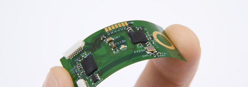
Flexible printed circuits are made from dielectric substrate film materials, such as polyester or polyimide, that can bend and twist without breaking. The design is simple, yet effective: a bare circuit with electrical traces etched onto the surface, coated with a protective overlay.
Flexible PCBs can be single-sided, double-sided, or multi-layered. Some might have a hybrid rigid-flex design, depending on the specifications of your application.
Flexible Circuit Boards: The Pros
Thin, Lightweight, and Flexible
Flex circuits have a slim profile that allows them to twist, bend around corners, and conform to virtually any shape. This feature is ideal for applications involving small or tight spaces, or where circuits must be routed through components.
Additionally, flex circuit boards weigh less than rigid PCBs. This feature is beneficial for aerospace, wearable devices, and other applications where weight is a significant design factor.
Higher Shock and Vibration Resistance
Compared with rigid circuits, flex circuits can withstand more shock and are less prone to cracking under vibration. Under vibration or impact, the flexible design also reduces stress on the solder joints, helping minimize the risk of circuit failure.
Versatile Lengths
Flex printed circuits can be manufactured in lengths up to tens of meters, reducing the need for long cables and multiple sockets in a design. For this reason, many applications in the industrial, aerospace, and medical markets use flex circuits in place of complex cabling.
Eliminates the Need for Wiring Cable Harnesses
With a low profile and the ability to mold to almost any shape, flex circuits can replace wiring harnesses and the need for multiple connectors in a component. Reducing the number of connectors and PCBs optimizes space and minimizes connectivity issues.
Flexible Circuit Boards: The Cons
Higher Bare Circuit Cost and Longer Development Time
Flexible and rigid-flexible PCBs cost more to build and have longer build cycles than rigid circuits. However, for applications involving unique shapes, restricted spaces, or weight limitations, flex circuits are the best option regardless of cost.
Design and Stack-up Complexity
As the stack-up of a flexible PCB increases, so does its complexity. Follow these guidelines to prevent damage and malfunction:
- Never use plated through-hole vias in bend areas
- Avoid sharp 90-degree traces that will increase the likelihood of fracture
- Conductors smaller than 10mils must be placed on the inside of the neutral bend axis and should run perpendicular to the bend
- Conductors must be staggered on multi-layered circuits
Additional considerations include the types of coverlay, flexible solder masks, stiffeners, and adhesives used in the design. Each can increase costs and alter the board’s thickness.
The Pros and Cons of Flexible Circuits: The Final Word
As electronic components and devices get increasingly smaller, flexible PCBs easily accommodate the needs of slimmer and more compact designs without sacrificing the reliability or functionality of the circuit. We recommend working with an experienced PCB manufacturer who assesses Design for Manufacturability (DFM) and provides honest feedback on the best solutions for your application.
Tramonto Circuits has achieved a quality ratio of over 99% since 2008 and is one of the few U.S. manufacturers capable of producing long printed circuits. Learn more about our flex circuit technologies and discuss your concept with an engineer.